Keeping up with HMC Clinic project

o3 Deep Research’s clarification request:

This is a detailed and well-structured request. Before I proceed, could you clarify the following points to ensure completeness and accuracy:

  1. Procurement Links: Do you have a preference for specific suppliers (e.g., Amazon UK, scientific suppliers, industrial suppliers), or should I focus on general availability within Scotland?
  2. ElectroPioreactor Setup: Could you provide details about the electroPioreactor setup? Specifically, does it have built-in voltage/current control, and do you have any existing software for controlling electroplating parameters?
  3. Platinum Thickness: Do you have a target platinum thickness for the plating, or should I suggest a standard suitable for HOB research?
  4. Plating Solution: Do you already have a preferred platinum plating solution, or should I include recommendations for the best commercially available options?
  5. Surface Preparation: Should I include a standardised cleaning/polishing protocol for the titanium rods before plating?
  6. Measurement Verification: Should I include recommendations for verifying the plating thickness and uniformity (e.g., SEM, EDX, weight measurement)?

Let me know, and I will start compiling a detailed, structured report with all the required sections.

My clarification:

  1. Amazon.co.uk, cpc.farnell.com and similar reputable online UK retailers would be great.

  2. Please see HOB Enrichment | AMYBO and its links for details of the electroPioreactor. Before starting the rest of the research please let me know if that gives you all the information you need?

  3. Please determine standard thicknesses in the literature.

  4. Please recommend the best commercially available plating solutions.

  5. Yes, please provide optimal surface preparation methodology

  6. Yes, please provide both low cost and money now object recommendations for plating thickness and uniformity measurement.

o3 Deep Research main response (part 1 of 3)

Thanks for the detailed clarifications. I will now conduct research to compile a structured manual covering all aspects, including:

  • A tools and materials section listing required equipment, procurement links, and cost estimates from Amazon UK, CPC Farnell, and other reputable UK retailers.
  • A review of electroPioreactor suitability based on the provided documentation, assessing whether it can be used for platinum plating or if a bench power supply is preferable.
  • A literature review to determine standard platinum plating thicknesses for similar applications.
  • Recommendations for the best commercially available platinum plating solutions.
  • An optimal surface preparation methodology for titanium rods to ensure consistent plating.
  • Guidance on plating thickness and uniformity measurement, with both low-cost and high-end options.
  • Instructions for producing 12 matched electrodes for comparative academic trials.
  • A cost-effective method for producing 2 matched electrodes using an electroPioreactor, including whether a bench power supply adds significant advantages.

I’ll get back to you once I have compiled the findings into a detailed report.

1. Tools and Materials

To achieve consistent platinum plating on titanium rods, prepare the following tools and consumables. Items are grouped by function, with purchase options (UK suppliers) given per the cost categories:

  • Titanium Rods (6 mm diameter, Grade 2 or 5): 60 mm length rods (or longer rods cut to size) serve as the electrode base. Look for high-purity (≥99.5%) titanium for corrosion resistance. For example, Goodfellow offers Grade 2 Ti rods (6 mm Ø, 99.6+% purity) (Titanium, rod, 100mm, diameter | GF04311638-1EA). Packs of small rods are available online (e.g. uxcell 5 × 100 mm GR5 rods for ~£15–£30) (uxcell 5Pcs GR5 Titanium Rod, Dia 6mm 0.23" Length 100mm 3.94 …). Ensure rods are uncoated and cleaned of any grease or oxide (surface prep steps in Section 5).

  • Platinum Plating Solution: A high-quality platinum electroplating bath is critical for repeatable results. We recommend a ready-made tank plating solution containing platinum complexes (typically ~4 g Pt per liter) (P52510 | Platinum Plating Solution) for consistent deposition. For instance, a 1 L platinum plating solution (plating range 0.2–20 µm) is ~£195 (P52510 | Platinum Plating Solution). Smaller volumes are available: Spa Plating (Goldn) sells 50–250 mL Platinum Tank Plating Solution (UK) for ~£23–£114 (inc. VAT) (Platinum - Electroplating equipment). These commercial solutions are formulated for uniform, adherent plating. (Items over £50: 1 L plating solution; Items £10–£50: 50–250 mL solution options.)*

  • Plating Anode (Inert Counter Electrode): Use a platinum-coated or platinum mesh anode to complete the circuit during electroplating. An expanded platinized titanium mesh is ideal – e.g. small strips of platinized Ti mesh can be obtained for <£10 (Evaluating platinized electrodes for electrolysis - Development - AMYBO.org). A higher-quality option is a platinized titanium rod/plate from a reputable source (for example, a 6 mm × 85 mm platinized Ti electrode was ~£28.60 from Goldn including shipping (Evaluating platinized electrodes for electrolysis - Development - AMYBO.org)). The anode should have a pure platinum coating to avoid contaminating the bath. (Items under £10: eBay/Amazon Ti mesh strips; over £10: custom platinized Ti rods or larger mesh panels.)*

  • DC Power Supply (Adjustable): A stable bench-top DC power supply is recommended for controlling plating current/voltage. Choose a supply capable of ~0–30 V and ~0–5 A output with fine adjustment. Many lab power supplies fall in the £50–£150 range. For example, a single-channel 30 V/5 A supply with digital controls is ~£89 (£106 inc VAT) at CPC Farnell (72-2540 - Single Output DC Bench Power Supply with RS232 … - CPC). Amazon UK also offers popular 0–30 V, 5 A models around £60 (rated 4.6★, 200+ bought) (Bench Power Supply - Amazon.co.uk). Ensure the supply can operate in constant current mode (for uniform plating thickness). (Items over £50: bench PSU options from Tenma, Korad, etc.; £10–£50: smaller hobby supplies if budget-limited.)*

  • Electrical Leads and Connectors: To connect the titanium cathode and platinum anode to the power source, gather insulated wires and clips:

    • Alligator/Crocodile Clips for temporary connections (bundles of 10 are ~£5–£10). These allow attaching to rods or mesh easily.
    • Ring or fork crimp terminals (M4/M6 size) if bolting electrodes through lids (as in Pioreactor vial caps) (Bill of Materials? - Development - AMYBO.org). These ensure a secure, repeatable connection.
    • Banana plug leads compatible with your power supply outputs (often included with the PSU or ~£5 for a pair).
      (Items under £10: connector sets, clip leads – consider bundling multiple small items in one order to reduce shipping.)*
  • Plating Vessel: Use a chemically resistant container to hold the plating solution. For single electrodes, a glass beaker (100–250 mL) or polypropylene cup works well. For plating multiple electrodes or larger volumes, a wider glass dish or small tank is useful. Ensure the container is deep enough to immerse ~35 mm of the rod. (Glass beakers ~100 mL cost ~£2–£5 each, often sold in packs – bundle with other lab glassware to exceed £10 if needed.)

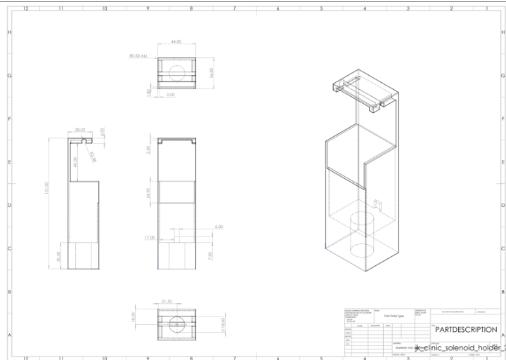
  • Positioning Jig/Holder: Devise a way to hold the titanium rod such that ~35 mm of its end is submerged in solution, without touching the container or anode. For instance, use a clamp stand or a 3D-printed vial cap (the AMYBO Pioreactor community provides a cap design for 6 mm electrodes (Evaluating platinized electrodes for electrolysis - Development - AMYBO.org)). You can also use alligator clips to suspend the rod, but ensure consistent immersion depth. Mark the 35 mm length on each rod and mask above it (e.g. with PTFE tape or lacquer) to prevent accidental plating beyond the target area.

  • Cleaning Supplies: Proper cleaning is crucial (detailed in Section 5). Prepare:

    • Degreasing solvent – e.g. acetone or isopropanol (lab-grade, £10–£20 per liter) to remove oils.
    • Detergent – mild laboratory detergent or dish soap for ultrasonic cleaning (if available).
    • Abrasion materials – fine grit abrasive paper or sandpaper (400–600 grit, a few pounds) to roughen the titanium surface slightly if needed.
    • Acid for etching – see Section 5; may include nitric acid (~£15 for 500 mL) and HF or a substitute (HF requires specialized procurement and handling, see safety). Alternatively, oxalic acid (~£10/kg) or ammonium bifluoride (~£20/500 g) can be used for surface activation (often available from chemical suppliers). (These chemicals are hazardous; ensure proper facilities – they are typically stocked in labs, not general retailers.)
  • Safety Equipment: Always have appropriate PPE when handling plating solutions and acids:

    • Nitrile or neoprene gloves (disposable nitrile gloves are ~£5–£10 per box) (Bill of Materials? - Development - AMYBO.org). Use heavy-duty gloves when working with HF or hot acids.
    • Eye protection – chemical splash goggles (£5–£15) and/or a face shield if using HF.
    • Lab coat or apron to protect skin and clothing.
    • If using HF: calcium gluconate gel (emergency antidote for HF burns) should be on hand, and a fume hood is required.
      (Items under £10: basic PPE like gloves, goggles can be bundled; over £10: specialized HF-resistant gloves or fume handling equipment if needed.)
  • Optional Equipment:

    • Ultrasonic Cleaner – for superior cleaning of the titanium surface (small 1–2 L ultrasonic baths are ~£50–£100). Ultrasonic agitation in detergent helps remove grime and oxide.
    • Magnetic Stirrer or Agitation – gentle stirring of the plating solution during deposition can improve uniformity. A stir plate (~£30–£80) or even manual periodic agitation can be used. Not strictly required for small electrodes, but recommended for consistent results across labs.
    • Analytical balance (0.1 mg resolution) – to measure the rod’s weight before and after plating for thickness calculations (many labs have one; if not, these are >£100). Alternatively, a high-precision scale (±0.001 g) around £50–£100 can serve for gravimetric analysis of plating thickness.

By assembling the above, you will have the necessary setup to plate titanium electrodes consistently. The listed procurement options (Amazon, CPC/Farnell, etc.) help ensure each lab can obtain similar equipment, promoting reproducibility. In particular, using the same plating solution brand and controlling plating current via a proper power supply are key to identical results across sites.

2. ElectroPioreactor Suitability for Plating

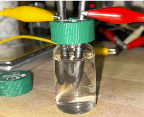
The electroPioreactor (as described in the AMYBO HOB Enrichment setup) is a small bioreactor system designed to cultivate microbes with in-situ electrolysis (Evaluating platinized electrodes for electrolysis - Development - AMYBO.org) (Evaluating platinized electrodes for electrolysis - Development - AMYBO.org). It typically consists of a 20 mL culture vial with electrode ports and is controlled by a Raspberry Pi (via the Pioreactor hardware) (Bill of Materials? - Development - AMYBO.org) (Bill of Materials? - Development - AMYBO.org). One question is whether this system’s built-in electronics can double as a plating power source, eliminating the need for a separate bench supply.

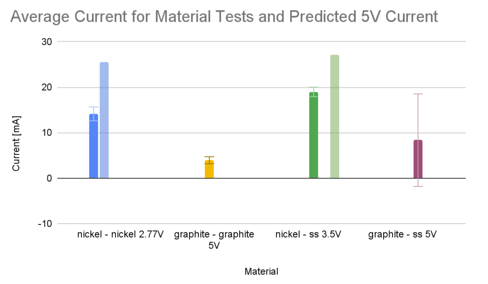
Capabilities of the ElectroPioreactor: In the Pioreactor setup, one of the LED control channels was repurposed to drive current through electrodes (Evaluating platinized electrodes for electrolysis - Development - AMYBO.org). For example, channel D (normally an LED output) was set to 10% intensity to perform water electrolysis using a platinized Ti anode and stainless cathode (Evaluating platinized electrodes for electrolysis - Development - AMYBO.org) (Evaluating platinized electrodes for electrolysis - Development - AMYBO.org). This indicates the Pioreactor can source some DC current (likely via a transistor or LED driver circuit) to the electrodes. Users observed gas bubble formation and changes in solution, confirming that the Pioreactor can deliver current for electrochemical reactions (Evaluating platinized electrodes for electrolysis - Development - AMYBO.org) (Evaluating platinized electrodes for electrolysis - Development - AMYBO.org). However, the exact current/voltage output is limited by the Pioreactor’s design:

  • The LED drivers are designed for low-power LEDs, so the maximum current is likely in the tens of milliamps range (each channel possibly up to ~20–40 mA unless modified).
  • The output voltage is constrained (probably 5 V or less, as it’s powered by USB/5 V). This may only support plating small areas at low current density.
  • Control is via PWM “intensity” settings rather than a true constant-current or constant-voltage mode. This makes it harder to precisely control plating conditions. In Gerrit’s test, 10% LED intensity was used arbitrarily; a different unit or channel might deliver a slightly different current at “10%”.

Can it be used for electroplating? It is possible to plate with the ElectroPioreactor’s output, but it is suboptimal. For very small-scale plating (one or two electrodes) and if no bench supply is available, one could attempt to use the Pioreactor:

  • Place the titanium rod (cathode) and a platinum anode in the Pioreactor vial filled with plating solution.
  • Connect them to one of the Pioreactor’s channels (as done for electrolysis) (Evaluating platinized electrodes for electrolysis - Development - AMYBO.org).
  • Use the software to set a certain PWM intensity to drive plating current, and run for a longer duration to deposit the desired platinum thickness.

However, there are significant limitations:

  • Limited Current & Speed: The low current means plating will proceed slowly. For instance, achieving a few microns of platinum might take many hours, whereas a bench supply could do it in minutes with higher current. Long plating times increase the risk of uneven deposition (due to solution depletion near the electrode, etc.).
  • Lack of Feedback Control: The Pioreactor cannot easily regulate exact current or measure plating progress. A bench supply provides constant current mode and readouts of voltage/current, ensuring repeatable conditions. Without this, each lab’s Pioreactor might output slightly different currents for the same “intensity” setting, leading to variability.
  • Potential Hardware Strain: Running the Pioreactor LED driver at high output for extended periods (to plate) could overheat or stress it, since it wasn’t intended as a power supply. It might also introduce electrical noise into the Pioreactor’s sensing circuits (since it’s tied to LED control channels).

Assessment: The electroPioreactor is not ideally suited for electroplating beyond very rudimentary trials. It lacks the precision and power needed for consistent plating thickness and quality. In the AMYBO forum, project members themselves leaned toward using proper plating equipment – Martin suggested possibly plating titanium bolt anodes within a Pioreactor vial but using established plating methods (Evaluating platinized electrodes for electrolysis - Development - AMYBO.org). The consensus was that a dedicated plating process (potentially with an external supply) would be more reliable.

Bench Power Supply vs. Pioreactor: For standardized results across multiple labs, a bench power supply is preferable. It offers:

  • Precise control: You can set the exact current (e.g. 50 mA) or voltage needed. This ensures each electrode sees the same conditions, crucial for repeatability.
  • Higher current output: Allows plating at optimal current density for good adhesion and uniformity, and can plate faster. For example, if plating at 5 mA/cm² on a ~6.6 cm² area (35 mm of 6 mm rod), ~33 mA is needed – within a bench supply’s capability, but possibly near the upper limit of the Pioreactor channel.
  • Stability: Bench supplies provide steady DC with minimal ripple, whereas the Pioreactor’s PWM might introduce pulsating current (unless filtered), potentially affecting deposit quality.

In summary, while an ElectroPioreactor can technically be repurposed for small-scale plating in a pinch, it is suboptimal for consistent, reproducible plating. Using it might be justified for a cost-effective trial of 1–2 electrodes (see Section 8), but for producing a set of identical electrodes across labs, a proper bench supply is strongly recommended. The slight added cost is justified by the improved control and repeatability of the plating process (Evaluating platinized electrodes for electrolysis - Development - AMYBO.org). Notably, community feedback from Spa Plating’s expert indicated that if regular electrode production is needed, investing in proper plating setup (or even making your own plating rig) is worthwhile (Evaluating platinized electrodes for electrolysis - Development - AMYBO.org).

Conclusion: The ElectroPioreactor is a clever multi-functional device for microbial experiments, but for platinum plating, use it only if no alternatives exist. For optimal and standardized results, use a dedicated DC power supply in a controlled plating setup, and keep the ElectroPioreactor for its primary purpose of culturing and monitoring HOB.

3. Standard Platinum Plating Thickness

In designing platinized titanium electrodes, one must decide on the target platinum coating thickness. Standard practice from literature and industry indicates that a few microns of platinum on the titanium substrate are sufficient for durable, inert electrodes:

  • Typical Thickness: Platinized titanium anodes commonly carry a platinum layer around 2.5 µm thick (Microsoft Word - Surface World Article - Web Copy 27.03.07.doc). This thickness has become a de-facto standard for many applications (e.g. in electrolysis, electroplating anodes, cathodic protection) because it provides an excellent balance of conductivity, catalytic performance, and longevity (Microsoft Word - Surface World Article - Web Copy 27.03.07.doc) (Microsoft Word - Surface World Article - Web Copy 27.03.07.doc). At ~2–3 µm, the platinum completely covers the substrate, ensuring the titanium is not exposed to corrosive environments during use.

  • Rationale: A 2–3 µm Pt coating is thick enough to behave like bulk platinum in electrochemical behavior (low overpotentials, high corrosion resistance), but thin enough to minimize platinum usage (Pt is expensive) and stress from thermal or mechanical mismatch. Thinner coatings (<1 µm) may work initially but tend to have microscopic porosity or pinholes; titanium could oxidize through these gaps and cause delamination over time. Much thicker coatings (>5–10 µm) are generally unnecessary for lab-scale electrodes and would consume more platinum without significant performance gain, except in extremely long-life or high-load applications.

  • Industry Standards: Suppliers of platinized titanium often specify a minimum coating thickness and sometimes a range. For example, one manufacturer notes their platinum-coated titanium wire anodes have at least 0.1 µm Pt (with up to 20 µm max for special cases) (Platinum Coated Titanium Wire - Jennings Anodes). However, high-performance electrodes usually use coatings on the order of a couple of microns. Technical literature confirms that platinised Ti/Nb anodes are “covered with a few microns of platinum (usually 2.5 µm)” (Microsoft Word - Surface World Article - Web Copy 27.03.07.doc). This thickness yields a very low wear rate; e.g., in a typical chromic acid bath, platinum consumption can be as low as 1–4 g per million ampere-hours of operation (Microsoft Word - Surface World Article - Web Copy 27.03.07.doc), meaning a 2.5 µm layer can last for years in service.

  • Similar Applications: In microbial fuel cells, water electrolysers, or sensor electrodes, reported platinum layer thicknesses are generally in the low-single-digit micron range. Academic papers and patents that discuss creating Pt/Ti electrodes often aim for ~1–5 µm Pt. For instance, a reference for platinum-coated titanium anodes in chlorine generation found that a few microns was sufficient, with optional post-deposition annealing to improve adhesion (Titanium platinum plating question | Gold Refining & Metal Extraction Forum) (Titanium platinum plating question | Gold Refining & Metal Extraction Forum). Another source (Jennings) provides custom Pt coatings up to 20 µm for special needs (Platinum Coated Titanium Wire - Jennings Anodes), but such thick layers are rarely needed in typical HOB research contexts.

  • Platinum Black vs. Smooth Plating: Note that some applications use platinum black (a micro/nano-porous platinum deposit) to maximize surface area (e.g. electrodes in hydrogen fuel cells or sensors). Platinum black coatings are usually very thin in terms of dense equivalent (maybe 0.1–0.5 µm if compressed), but appear thicker due to porosity. In our context (electrolysis anodes for HOB cultures), platinum black is not ideal – it can introduce contamination and is mechanically fragile. We focus on a smooth, adherent platinum plate, ~microns thick.

Recommendation: Aim for a platinum plating thickness of about 2.5 µm as a standard. This is a proven thickness for platinized titanium electrodes (Microsoft Word - Surface World Article - Web Copy 27.03.07.doc), providing a durable coating that can withstand repeated autoclaving (if needed for sterilization), long-term electrolysis, and any required cleaning. It also ensures that electrodes made in different labs (following the same procedure) will have comparable performance. Thicker coatings (up to ~5 µm) can be used if longevity is a major concern and platinum supply is not an issue, but increasing thickness beyond ~5 µm yields diminishing returns in corrosion resistance (Platinum Coated Titanium Wire - Jennings Anodes). If plating is done correctly, even 1–2 µm can function; however, given possible slight variances in plating between labs, targeting ~2.5 µm provides a safety margin that all electrodes are fully coated.

Finally, document the intended thickness and tolerances in your protocol. That way, all labs know the goal (e.g. “Each titanium electrode is plated with 2.5 ± 0.5 µm of platinum”). This clarity helps when verifying the results (Section 6) and ensures a shared standard for “identical” electrodes worldwide.

TBC

o3 Deep Research main response (part 2 of 3)

4. Best Platinum Plating Solutions

The choice of plating solution greatly affects the consistency and quality of the platinum deposit. It is important to use a commercial, high-purity platinum plating solution that is formulated for repeatable results. Key considerations include the platinum chemical form, bath composition (acidity, additives), and ease of use. Here we outline the top options:

  • Acid-Based Platinum Baths (P-Salt or Similar): Most platinum electroplating solutions are based on chloroplatinic acid or platinum amine complexes (often called “P-salt”, e.g. platinum diamino dinitrite). These are typically used with a strong acid like sulfuric or sulfamic acid as supporting electrolyte (Titanium platinum plating question | Gold Refining & Metal Extraction Forum). A quality commercial solution will contain the correct concentration of Pt (usually 2–10 g/L) and proprietary additives that improve plating characteristics (throwing power, brightness, stress). For example, a ready-to-use platinum bath might contain ~4 g/L Pt as complex salt and plate deposits from 0.2 up to 20 µm with uniform thickness (P52510 | Platinum Plating Solution). This type of solution produces a dense, pure platinum layer (bright white to light grey in appearance) (P52510 | Platinum Plating Solution). We recommend using these standard platinum plating baths as they are well-characterized and free of hazardous additives like cyanide (common in gold plating, but not needed for Pt).

  • Recommended Commercial Solutions: Several reputable suppliers provide platinum plating solutions suitable for our application:

    • Spa Plating (Goldn)Platinum Tank Plating Solution. This UK-based supplier (Spa Plating Ltd.) is known for plating kits for hobbyists and researchers. Their platinum bath is designed for tank plating (immersive plating) and is available in small quantities (50 mL up to 250 mL) (Platinum - Electroplating equipment). Users in the AMYBO project have liaised with Spa Plating; the company even provided custom platinum-coated electrodes and pointed to their platinising process videos (Evaluating platinized electrodes for electrolysis - Development - AMYBO.org). Spa Plating’s solution is formulated for consistent deposition and good adhesion on difficult substrates. It’s a convenient choice, especially in the UK/EU, to ensure everyone is using the same solution chemistry. Purchase from their official site (goldn.co.uk) or authorized distributors.
    • Legor / Technoplate Platinum Solutions – Legor is an Italian company whose plating solutions are distributed worldwide (e.g. via Cousins UK, Rio Grande, Stuller, etc.). Their platinum plating solution (often called PTLUX or similar) is a high-quality bath used in the jewelry industry for decorative platinum plating. It produces uniform coatings and is free of nickel, lead, cadmium (P52510 | Platinum Plating Solution) (important for avoiding contamination). A 1 L bottle (with ~4 g Pt) is ~£195 (P52510 | Platinum Plating Solution). The Legor bath is known for bright, adherent platinum deposits and could be an excellent choice for research electrodes due to its reliability. If multiple labs coordinate, using the same batch of Legor solution would standardize results.
    • “Rhoduna PT One” (Platinum-Rhodium) Solutions: For completeness, some commercially available solutions are mixed metal (platinum-rhodium) intended as rhodium plating substitutes (Rhoduna® PT One Rhodium Platinum Plating Solution - TP1311). For example, Rhoduna PT One contains a small amount of platinum in a rhodium bath. These are not recommended for our purpose – they are meant for thin decorative coatings and contain rhodium (which we don’t need and which could alter electrode properties). Stick to pure platinum solutions unless a specific reason to alloy is identified.
    • Other Suppliers: Companies like Johnson Matthey and Metalor historically offered platinum plating concentrates (“P-salt” based). Canning/Enthone (now MacDermid Enthone) also had platinum baths. For global labs, ensure the solution is equivalent in concentration and type. If one lab must use a local product, verify the platinum content and operating conditions match those of the standard solution (P52510 | Platinum Plating Solution).
  • Solution Operating Conditions: The chosen plating solution will come with a technical data sheet. Adhering to its recommendations ensures consistency. Typical conditions for platinum plating:

    • Temperature: Many platinum baths operate at room temperature (20–30 °C). Some may allow slight heating (up to ~50 °C) to improve deposition rate or adhesion. Check the product guidelines – for example, Legor’s solution likely works at room temp (no special heating required), simplifying setup.
    • Current Density: Platinum plating often works in the range of 0.5–5 A/dm² (amps per square decimeter) depending on bath chemistry (Titanium platinum plating question | Gold Refining & Metal Extraction Forum). This roughly translates to 5–50 mA/cm². A moderate current density (e.g. ~10 mA/cm²) is a good starting point for a 2.5 µm deposit – it balances plating speed with deposit quality. Too high current can cause rough or dark deposits; too low can lead to poor adhesion. The solution manual will specify an optimum range.
    • Anodes: Use insoluble anodes with these solutions (usually platinized titanium or pure platinum anodes). Do not use a soluble platinum anode expecting it to dissolve to replenish platinum – Pt anodes are extremely corrosion-resistant and won’t appreciably dissolve under plating conditions (Microsoft Word - Surface World Article - Web Copy 27.03.07.doc). Thus, the bath’s Pt content will deplete after plating many parts; you’ll need to add replenisher or fresh solution eventually. For consistency, it’s best if all labs use fresh solution or solutions of the same age/usage level for a given experimental series.
  • Consistency and Durability: The recommended solutions produce pure platinum deposits that are adherent and stable. They do not include significant hardeners or brighteners (common in decorative plating) that could embrittle the coating. The result is a coating that behaves like bulk platinum – high melting point, insoluble in most acids, and non-reactive, which is ideal for in-culture electrodes. Over time, if the plating solution is reused, impurities could accumulate (especially if plating multiple electrodes in batches). To maintain consistency worldwide, labs should either:

    • Use new solution for each batch of electrodes or,
    • Implement a standard maintenance routine (e.g. carbon treatment, or filtering of the bath after use) and document how many electrodes have been plated with a given solution volume.

In summary, for best results use a commercial platinum plating solution from a reputable source, such as Spa Plating’s Platinum Tank solution or an equivalent high-purity bath. This ensures that every lab is effectively working with the same chemistry, minimizing variation. Avoid homemade concoctions or repurposed jewelry baths without validation – the goal is a proven solution with published parameters that everyone can follow for identical outcomes. By standardizing the plating solution, we eliminate one major source of variability in electrode fabrication.

5. Surface Preparation of Titanium Rods

Proper surface preparation of the titanium rod is arguably the most critical step to achieve a well-adhered, uniform platinum coating. Titanium is a reactive metal that forms a tenacious oxide layer (TiO₂) which can prevent metal plating from bonding. Therefore, we must thoroughly clean and activate the surface. Below is the step-by-step optimal procedure for prepping 6 mm Ti rods:

5.1. Mechanical Cleaning and Shaping:

  1. Cut to Length: Ensure each rod is cut to 60 mm length (if not already precut). Use a metal saw or cutting wheel suited for titanium. Deburr the cut edges with a file or sandpaper to remove any burrs or sharp edges.
  2. Mark Plating Area: Mark the rod at 35 mm from one end (this end will be plated). You can use a fine marker or a scoring tool. This is a guide; actual plating will only occur where the solution contacts, but marking helps with handling and masking.
  3. Surface Roughening (if needed): Lightly abrade the plating end (35 mm) of the rod with fine-grit abrasive paper (~400–600 grit). The goal is to create a matte surface by removing any heavy oxide and exposing fresh titanium. Do not overly scratch or gouge – just a gentle uniform matt finish. This can improve plating “keying” into the surface. Note: Some protocols skip mechanical abrasion and rely solely on chemical etch; however, a light abrasion can improve wetting and adhesion, especially if the Ti was very smooth or polished.
  4. Masking: Mask the upper part of the rod (the 25 mm that will not be plated) to keep it clean and unetched. Use acid-resistant tape (e.g. PTFE tape or polyimide Kapton tape) wrapped just above the 35 mm mark. Also mask the very tip of the rod if it’s not needed to be plated (optional; in most cases we plate the entire 35 mm end including the tip). Ensure no adhesive overlaps into the area to be plated.

5.2. Degreasing:
5. Solvent Wash: Clean the exposed titanium surface with a solvent to remove oils. Soak a lint-free wipe or cotton in acetone and thoroughly wipe the plating end. Alternatively, dip the rod in acetone for a few minutes. This removes grease, marker ink, and organic residues.
6. Detergent Clean: Prepare a warm solution of lab-grade detergent or a few drops of dish soap in distilled water. Scrub the titanium end using a soft brush or toothbrush. If available: use an ultrasonic cleaner – submerge the rod in a beaker with the detergent solution and sonicate for 5–10 minutes. This knocks off fine particulates and any remaining oils.
7. Rinse: Rinse the rod very well in distilled (or deionized) water. It’s important to remove all soap and solvent residues. Hold the rod with clean tweezers or gloved hands (to avoid re-contaminating with skin oils).

  1. (Optional Check – Water Break Test): After rinsing, observe the water wetting on the titanium surface. A fully clean metal surface will allow water to form an unbroken film. If the water beads up significantly (“water break”), it indicates remaining oil – repeat the cleaning steps if so.

5.3. Chemical Etching (Activation):
This is the critical activation to remove the passive TiO₂ layer and expose fresh titanium for plating. Caution: These steps involve corrosive acids. Wear proper PPE and work in a ventilated area or fume hood.

There are a few methods; the optimal one uses a brief HF-containing etch. If HF use is possible in your lab, follow Method A. If HF is not allowed, use Method B (slightly less effective, but safer).

  • Method A: Acid Pickle with HF/HNO₃ (Preferred if possible) – This is a common activation for titanium:

    1. Prepare a pickling solution of hydrofluoric acid and nitric acid. A typical mixture (from literature and industry practice) is: HF (40%) 50 g/L and HNO₃ (67%) 400 g/L in water (Titanium platinum plating question | Gold Refining & Metal Extraction Forum). In simpler terms, roughly 1 part concentrated HF to 8 parts concentrated nitric, diluted in ~10 parts water. Example: 50 mL HF + 400 mL HNO₃ + 550 mL water. Always add acids to water and HF last. This mixture will vigorously attack oxides and slightly etch titanium metal.
    2. At room temperature, immerse the titanium end into the pickle solution for about 1–2 minutes (Titanium platinum plating question | Gold Refining & Metal Extraction Forum). You will see bubbling as the oxide dissolves. Do not exceed ~2 min to avoid excessive metal loss.
    3. Remove the rod and immediately rinse in copious distilled water. It’s crucial to wash off all HF/HNO₃. Do not allow the rod to dry with acid on it – rinse directly from the acid into water.
    4. (Optional) Follow with a second dip in a hot de-oxidizing acid: e.g. boiling in 5–10% oxalic acid for a few minutes (Titanium platinum plating question | Gold Refining & Metal Extraction Forum). This can further remove any remaining films and help condition the surface. Rinse again.

    This HF/Nitric treatment aggressively removes the oxide and activates the surface. Many successful Pt plating processes on Ti use exactly this step (Titanium platinum plating question | Gold Refining & Metal Extraction Forum) (Titanium platinum plating question | Gold Refining & Metal Extraction Forum). Ensure you proceed to plating (or at least the strike plating) immediately after this activation to avoid re-oxidation (titanium will form a new oxide layer within minutes in air).

  • Method B: Fluoride Activation without HF – If HF is too hazardous or unavailable, a substitute is to use ammonium bifluoride (NH₄HF₂) or fluoride salt in acid:

    1. Prepare a solution of ammonium bifluoride ~10 g/L in 10% sulfuric acid (Titanium platinum plating question | Gold Refining & Metal Extraction Forum). Heat to about 50–60 °C to increase effectiveness, or use it at room temp for a longer time.
    2. Immerse the titanium end for ~5–10 minutes. The fluoride will slowly attack the oxide, and the acidic environment helps.
    3. Alternatively, use a solution of oxalic acid (80–100 g/L) at boil, as tried in experiments (Titanium platinum plating question | Gold Refining & Metal Extraction Forum). Boil the rod in that solution for ~10–15 min. Oxalic acid can chelate titanium and remove oxide to some extent.
    4. Rinse thoroughly in distilled water.

    This method is gentler and safer (ammonium bifluoride releases some HF in solution, but in a controlled manner). However, the titanium surface may not be as active as with the strong HF dip. It may suffice for plating if followed immediately by a plating strike. It’s recommended to not skip at least some fluoride-based activation; titanium surfaces treated only with nitric or hydrochloric acid without fluoride often still don’t plate well (the oxide isn’t fully removed).

5.4. Immediate Plating or Strike:
After the acid activation, do not delay. The rod should go straight into the plating bath (or a pre-plating strike bath) within minutes of etching:

  • If you have a separate platinum strike solution (a dilute plating bath used for initial seeding), use it as per instructions. Most will simply use the main plating solution for both strike and plate.
  • Keep the rod wet from the rinse; do not dry it (drying can allow oxygen to form oxide). It’s okay if some water is on it as it goes into the plating solution – the small amount will be inconsequential in a reasonably sized plating bath.

5.5. Summary of Key Points for Prep:

  • Cleanliness is paramount: any grease or oxide will cause poor adhesion (the Pt can flake off easily). The rod should be chemically clean and active.
  • Use fresh gloves and clean tools for handling post-etch. Avoid touching the etched area with fingers or contaminated tweezers.
  • Consistency: All labs should follow the same prep protocol. The biggest variability in plating often comes from surface prep differences. By standardizing on, say, “abrade, solvent clean, HF/HNO₃ dip 60 s, rinse, plate immediately”, you ensure everyone’s titanium surface is in a similar state at the moment of plating.

Safety Notes: HF is very dangerous (causes deep burns and systemic toxicity). Only use it if trained and with proper facilities (fume hood, Ca-gluconate gel on standby). If labs cannot use HF, Method B provides a workable alternative using more benign chemicals. Even with Method B, wear gloves and eye protection; ammonium bifluoride and hot acids can also cause injuries.

By meticulously preparing the titanium surface as above, you create the ideal conditions for the platinum to adhere strongly rather than just “paint on”. A well-prepared titanium will yield electrodes that withstand handling, sterilization, and long-term operation without the platinum layer peeling or flaking.

6. Plating Thickness and Uniformity Verification

After plating the titanium rods with platinum, it’s important to verify that the coating thickness is as intended (~2.5 µm, or your target) and that it’s uniform along the 35 mm plated section. We outline both low-cost methods suitable for basic labs and high-end methods for thorough characterization:

6.1. Low-Cost Verification Methods:

  • Gravimetric Calculation (Weighing Method): This is an accessible way to estimate average plating thickness:

    1. Weigh each rod before plating (after prep and drying) using a precision balance. Record the weight.
    2. Weigh the rod after plating (and rinsing/drying). The difference in weight is the mass of platinum deposited.
    3. Calculate the thickness using the formula derived from volume = mass/density. The surface area plated is the cylindrical area (excluding masked parts) plus the tip if plated. For a 6 mm diameter rod, 35 mm length: area ≈ 6 mm × π × 35 mm = 659 mm² (not counting the circular end of ~28 mm², add that if tip plated). Convert to cm² (6.59 cm² for side, 0.28 cm² for tip).
    4. Platinum density is 21.45 g/cm³. So thickness (cm) = mass of Pt (g) / (density * area (cm²)). For example, if 0.035 g Pt was deposited on 6.59 cm², thickness = 0.035 / (21.45 * 6.59) = 0.000245 cm = 2.45 µm.

    This method effectively applies the known relationship: mass = area × thickness × density (How to Estimate Gold Content in Gold Plated Parts - A.G. Metals). It provides an average thickness over the entire plated area (MEASURING THE THICKNESS OF THE SILVER LAYER WHEN …). Do this for each electrode – identical plating runs should show very similar mass gains (within a few milligrams). If one electrode gained significantly less or more mass, that indicates a plating issue (e.g. contact problem or different current distribution).

  • Visual and Microscopic Inspection: Examine the plated surface:

    • Color/Appearance: A properly plated platinum layer will be metallic and silvery. It might be matte gray or slightly shiny white depending on plating parameters. Any discoloration (brown, black) or patchiness suggests problems (burnt deposit or thin areas). The AMYBO test noted that a failing electrode caused solution discoloration and itself looked “worse for wear” (Evaluating platinized electrodes for electrolysis - Development - AMYBO.org), whereas a good Pt electrode stayed bright (Evaluating platinized electrodes for electrolysis - Development - AMYBO.org) (Evaluating platinized electrodes for electrolysis - Development - AMYBO.org).
    • Uniformity along length: Check if the plating is even from the tip to the 35 mm mark. Non-uniform current can cause gradients (e.g. thicker at the tip if it’s closer to the anode). If one end looks noticeably different, adjustments in anode placement or agitation might be needed. All labs should note any such visual cues for uniformity.
    • Microscope Check (if available): Under a 10x or 20x magnification (stereo microscope or a loupe), examine the surface texture. It should look continuous. You may see tiny nodules (common in electroplated Pt) but you should not see exposed titanium (which would look darker/different). If you have access to a metallographic microscope, you could cross-section one sacrificial rod to measure the coating – but this destroys that sample, so gravimetric or XRF methods are preferred for routine checks.
  • Thickness Gauges: There are affordable handheld coating thickness gauges, but most work on ferrous/non-ferrous magnetic properties (for paint on steel, etc.) and are not suitable for Pt on Ti (both are non-ferromagnetic metals). Eddy current probes calibrated for non-magnetic coatings on non-magnetic substrates exist but are expensive. So, most low-cost gauges won’t help here.

  • Adhesion Tests: While not a direct thickness measurement, a simple adhesion test ensures the plating is sound. Gently try to scrape the surface with a plastic spatula or apply tape and peel. A well-adhered 2–3 µm platinum won’t budge or flake under tape (assuming surface prep was done well). If plating flakes off easily, something went wrong in prep or plating (and thickness might effectively be zero in places). Perform this test on one of the electrodes (or a test piece) – it’s a quick qualitative check for uniform coverage.

6.2. High-End Verification Methods:

  • X-Ray Fluorescence (XRF) Analysis: XRF is a non-destructive method widely used for coating thickness measurement (Plating Thickness Measurements - Applied Technical Services). An XRF analyzer can be calibrated to measure platinum thickness on titanium by detecting the intensity of Pt X-rays vs Ti substrate X-rays. Many plating shops or material labs have XRF equipment (following ASTM B568 for plating thickness (ASTM B568 - Plating Thickness By XRF Testing Services |)). XRF can measure even sub-micron coatings with good accuracy and can be done at multiple points along the rod to check uniformity. If resources allow, send one or two sample electrodes for XRF testing – it will confirm thickness (e.g. “2.4 µm Pt on Ti”) and uniform coverage. This is the gold standard for nondestructive testing (How to Measure Metal Coating Thickness Using Handheld X-ray …).

  • Electron Microscopy (SEM/EDS): For a detailed analysis, one electrode can be cross-sectioned (e.g. cut a small piece of the plated end) and examined in a Scanning Electron Microscope. The platinum layer will be clearly distinguishable, and one can directly measure its thickness in the SEM image. Energy-dispersive X-ray spectroscopy (EDS) can map Pt vs Ti to ensure there are no gaps. This method is destructive (sacrifices the sample piece), but provides visual confirmation of thickness and adhesion (you may see if there’s a clear interface or any delamination). This is likely overkill for routine checks, but could be done by one lab and shared as a reference with others (e.g. “SEM shows ~2.5 µm dense Pt, with good adhesion”).

  • Coulometric Stripping (Destructive): This method involves stripping the platinum off by electrochemical dissolution while monitoring charge. There are instruments that do this for plating thickness (often used for zinc or nickel plating tests). Platinum can be dissolved anodically in aqua regia or a specific electrolyte; the charge required corresponds to the metal mass, thus thickness. Given platinum’s noble nature, this isn’t as straightforward as for less noble metals, and it destroys the coating. It’s generally not used unless you specifically want to test one sample thoroughly.

  • Precision Mechanical Measurement: If one has a high-precision micrometer (resolution 1 µm or better) and a consistent way to measure the rod diameter, one could measure diameter before and after plating. The diameter increase will be twice the coating thickness. For example, a 6.000 mm rod might become 6.005 mm if 2.5 µm plating (because 2×2.5 µm = 5 µm diameter increase). This requires extremely precise instruments and temperature control (to avoid thermal expansion differences). It’s generally at the edge of what affordable tools can discern (220 Methods of Thickness Test for Plate Coating), so we don’t rely on this except as a rough sanity check if such micrometers are at hand.

6.3. Uniformity Considerations:

  • When plating multiple electrodes together (or sequentially in the same bath), uniformity between electrodes is also important. Compare the weights of all electrodes: they should be within, say, ±5% of the average if plating was consistent. If one is an outlier, investigate if its position or connection was different.
  • In use, a uniform platinum coating means each electrode will behave similarly in the electroPioreactor (e.g. similar overpotential for hydrogen or oxygen evolution). If one electrode had thinner coating, it might show higher voltage or some corrosion of Ti. So verification isn’t just academic – it directly ties to experimental reproducibility.

Documentation: Each lab should document the plating thickness verification for their batch. For example, record pre/post weights and calculate thickness for a couple of electrodes, and maybe include a photo under magnification. This provides confidence that “Lab A’s electrodes” and “Lab B’s electrodes” truly have the same platinum loading. If any lab finds discrepancy, they can adjust their process (time or current in plating) accordingly.

By employing these verification methods, both simple and advanced, we can ensure that the electrodes meet the design specification (e.g. a ~2.5 µm Pt coating uniformly on 35 mm of each rod). Consistent verification across labs closes the loop in standardizing the electrode production.

TBC

o3 Deep Research main response (part 3 of 3)

7. Producing 12 Matched Electrodes for Academic Trials

When producing a larger batch (e.g. 12 electrodes) for multi-lab trials or comparative experiments, the process must be highly repeatable so that all electrodes are as identical as possible. Below is a detailed, repeatable method for plating 12 titanium rod electrodes in one run or in consistent sub-batches:

7.1. Batch Preparation:

  • Material Prep: Obtain 12 titanium rods from the same source lot if possible to ensure identical composition and surface condition. Number or mark each rod (e.g. 1–12) on the unplated end for tracking.

  • Follow Surface Prep (Section 5) meticulously for each rod: It’s best to process all rods together in each step to maintain consistency. For instance, degrease all 12, then etch all 12 in one acid bath (using a holder or doing a few at a time in quick succession). Use fresh cleaning solutions as needed (don’t let one rod’s dirt redeposit on another). If using HF etch, you can dip multiple rods at once using a Teflon rack or by holding several with PTFE string—just ensure equal exposure time (Titanium platinum plating question | Gold Refining & Metal Extraction Forum).

  • Setup Plating Bath: Use a plating vessel large enough to accommodate all 12 rods at once or be prepared to plate in smaller batches (e.g. 3–4 at a time) with identical conditions. Plating all 12 simultaneously is ideal for uniformity, but requires a bit more setup:

    • Arrange an inert anode (or multiple anodes) so that each cathode (Ti rod) “sees” a similar anode-to-cathode distance. For example, you can use a platinized titanium mesh sheet bent into a cylindrical shape surrounding the rods, or a pair of mesh strips on either side of a row of rods, to provide even current distribution.
    • Mount the 12 rods on a non-conductive rack or holder. Ensure they are parallel, separated (no touching each other), and all dipped to the same depth (35 mm). A possibility: drill 6 mm holes in a plastic bar as a holder, or 3D-print a jig, to hold rods in place.
    • Connect all rods electrically together to the power supply’s negative output. This can be done by clamping all their unplated ends with a single bus bar or using wires that join to a common node (make sure the contact resistance to each rod is low and similar – tighten screws or clips firmly).
    • Essentially, you create a “cathode tree” of 12 identical parts.
  • Solution Volume: Use a sufficient volume of plating solution so that the total platinum in solution can plate all rods without significant depletion. For 12 rods at ~0.035 g Pt each (for ~2.5 µm), that’s ~0.42 g Pt total. If your solution has 4 g/L, use at least 0.5 L (which has ~2 g Pt) so that even after plating, plenty of Pt remains in solution (and the concentration drop is at most 20%). This ensures plating rate doesn’t slow toward the end and all rods get the same environment. Alternatively, if using a smaller volume, you may need to replenish the solution with concentrate after a certain number of rods – but in one simultaneous batch, that’s not possible, so better to use a sufficiently sized bath initially.

7.2. Plating Process (for batch):

  • Constant Current Plating: For best uniformity, use a constant current source and divide the current among the 12 rods. First, calculate the total area to be plated: one rod ~6.59 cm² (side) + ~0.28 cm² (tip) ≈ 6.87 cm². Twelve rods ~82.5 cm² total. Decide on a current density (say 10 mA/cm² as a moderate value). That would require ~0.825 A total current for 82.5 cm². Set the power supply to current-control mode at 0.825 A. If your supply can’t output that high, use a lower current density (5 mA/cm² → 0.412 A total). Make sure the anode area is ample so it can supply this current without polarization issues (platinum mesh has high capacity).

  • Begin Plating: With rods immersed and all connections double-checked, turn on the current. Bubbles (hydrogen at cathodes) will evolve; gentle agitation helps dislodge them so they don’t cause bare spots. You can manually stir the solution or use a magnetic stir bar. Ensure all rods are bubbling similarly – this is a visual cue that current is distributed evenly.

  • Time Control: Plate for the calculated time to reach desired thickness. Using Faraday’s law: the charge (Q) needed = area × thickness × density × (F/z/M) basically, but easier is to use the known plating efficiency if given. Many platinum baths have ~>90% cathode efficiency. For simplicity, one can empirically time based on earlier single tests or weight targets. For example, if one rod needed 15 minutes at 10 mA/cm² to get ~2.5 µm, then 12 rods at same current density also need ~15 minutes (since each cm² gets the same current density, the plating rate per area is the same). Monitor the process but avoid stopping midway (an interruption can sometimes cause oxidation or slight variation unless handled carefully).

  • Rotation (if needed): If you suspect slight unevenness (rods closer to an anode plate might get more current), you can rotate the rod holders halfway through plating to even it out – but if the anode setup is symmetric, this shouldn’t be necessary.

  • Completion: Once the time or charge is reached, turn off the current. Do not over-plate excessively as very thick deposits can introduce stress. Remove the rods from the bath promptly.

  • Rinsing: Immediately rinse all plated rods in a large volume of distilled water. This removes residual acidic solution and prevents any chemical attack or staining. Then rinse in deionized water. Handle rods gently; though platinum is deposited, it’s best not to knock them together to avoid any potential mechanical damage when freshly plated.

  • Post-Treatment: Some platers recommend a post-plating heat treatment for adhesion (e.g. annealing in hydrogen at ~700 °C as mentioned in literature for Pt/Ti) (Titanium platinum plating question | Gold Refining & Metal Extraction Forum) (Titanium platinum plating question | Gold Refining & Metal Extraction Forum). However, this is usually not feasible in most labs and likely unnecessary if prep and plating were done well. Our electrodes should have good adhesion as-is. You may simply dry the rods (air dry or gentle blow dry). If any plating solution components tend to stain, a dip in very dilute nitric acid can neutralize residues (though with modern platinum baths this isn’t usually an issue).

7.3. Ensuring Reproducibility:

  • Characterize one or two rods: Take weight measurements of a couple of rods to ensure thickness met the target (Section 6). If the result is slightly off, you can adjust plating time for the next batch.

  • Uniformity Check: All 12 should look identical. Compare their appearance and weight. If one rod appears different, you may have had a contact issue on that rod – this needs addressing before the next run.

  • Document the Process: Write down the exact parameters used: solution type and volume, current (or voltage) and time, temperature, agitation method. This recipe should be followed by other labs. Encourage each lab to replicate these conditions as closely as possible. For instance: “Plated 12 electrodes simultaneously at 5 mA/cm² for 30 min at ~25 °C in 500 mL of Spa Plating solution, using a Pt mesh anode encircling the cathodes.” Such details help others match your process.

  • Batching vs Sequential: If a lab lacks the ability to do all 12 at once (maybe their power supply can’t source enough current or they only have a small beaker), it’s acceptable to plate in two or three batches. In that case, it’s vital to keep conditions constant:

    • Use the same solution (or same volume replenished to original concentration) for each batch.
    • Plate each batch for the same time and current density.
    • Perhaps swap the order of rods (don’t always put the same subset in the first batch) in case there’s slight solution depletion over batches.

    But ideally, design the plating setup so even small labs can do one batch. For example, plating 6 at a time (two batches) is workable – still, all 6 in a batch should be uniform, and you’d compare batch1 vs batch2 by weight to ensure consistency.

7.4. Cross-Lab Consistency:

  • Once Lab A produces 12 electrodes, Lab B in another location should attempt the same protocol. They should compare notes: e.g., weights of their electrodes, visual appearance, any differences. Minor discrepancies can be ironed out (maybe Lab B’s power supply was uncalibrated, giving slightly lower current – they might increase plating time by 2 min to compensate).

  • It might be wise for one lab to send a couple of electrodes to another as references. Alternatively, all labs send one electrode to a central facility for thickness measurement (via XRF or SEM). This external validation can certify that “all labs achieved ~2.5 µm ±0.2 µm plating” – boosting confidence in experimental data obtained with those electrodes.

  • In the AMYBO context, the community’s collaboration (as seen with sharing designs and Spa Plating’s input (Evaluating platinized electrodes for electrolysis - Development - AMYBO.org)) is valuable. If one lab perfects the plating procedure, they should share any tips or slight modifications needed. Over a few iterations, a robust standard operating procedure (SOP) for making 12 matched electrodes will emerge.

By following the above method, you can reliably produce a dozen platinum-plated Ti electrodes that are virtually identical. These can then be distributed to different research groups, used in parallel experiments, or kept as spares – all with confidence that each electrode is equivalently manufactured. This level of consistency is crucial for academic trials comparing results across different locations.

8. Producing 2 Matched Electrodes Using an ElectroPioreactor

For small-scale needs – say you want to make just a pair of electrodes for a pilot experiment or to test the feasibility – you might consider using the ElectroPioreactor itself as a mini-plating setup to save cost. This section outlines a cost-effective methodology for plating a pair of electrodes and assesses using the electroPioreactor versus a bench supply in this scenario.

8.1. Setup for 1–2 Electrodes in the ElectroPioreactor:

  • Using the Pioreactor Vessel: Leverage the 20 mL vial and cap designed for electrolysis. The community has a vial cap design with a hole for a 6 mm electrode (Evaluating platinized electrodes for electrolysis - Development - AMYBO.org), which is perfect for holding your titanium rod. Print or obtain this cap, and mount the titanium rod (to be plated) through it so that ~35 mm extends into the vial. For the counter electrode, you can use a small platinized titanium mesh or the second titanium rod (though if the second rod is also to be plated, you’d have to configure a way to plate one as cathode and use another as temporary anode, then swap).

  • Wiring: Connect the rod to the Pioreactor’s LED driver channel (for instance, channel D positive to the rod for cathode, and channel D negative to the counter electrode if the Pioreactor is sourcing current in that configuration as it did for electrolysis (Evaluating platinized electrodes for electrolysis - Development - AMYBO.org) – note, previously they connected platinized electrode to positive and SS to negative to generate hydrogen (Evaluating platinized electrodes for electrolysis - Development - AMYBO.org); for plating, the titanium rod must be the cathode (negative) so it receives platinum). You may need to invert connections: titanium rod on negative, platinum mesh on positive of channel D.

  • Plating Solution in Vial: Fill the vial with a small volume of platinum plating solution. 20 mL might be sufficient for a thin plating on one rod. Since volume is small, platinum concentration will deplete faster – consider using the highest concentration solution available or replenishing after one electrode. Alternatively, if you can get a slightly larger container (maybe a 50 mL tube) that still fits in the Pioreactor heater/stir base, that could allow ~30–40 mL solution.

  • Parameters: Set the Pioreactor to drive current. For example, start with a low LED intensity (e.g. 10–20%) as per the earlier electrolysis tests (Evaluating platinized electrodes for electrolysis - Development - AMYBO.org). You might need to determine empirically what current that corresponds to. One approach: connect a multimeter (in series or use a shunt resistor) to measure the actual current at a given setting (e.g. 10% gave X mA). Suppose 10% intensity yields ~10 mA through the electrode pair – that might be ~1.5 mA/cm² for a 6.59 cm² area (very low). You may increase intensity to max (100%) if needed. If 100% corresponds to, say, 50 mA (this is hypothetical), that would be ~7.6 mA/cm² – which might plate slowly but at least reasonably.

  • Plating Procedure with Pioreactor:

    1. Clean and etch the titanium rod as in Section 5 (do this outside the Pioreactor).
    2. Insert it into the cap/vial with plating solution. Insert the anode (mesh) as well – maybe attach it to another port on the cap or dangle it in solution without touching the Ti rod.
    3. Start the current via Pioreactor software. Let it run for an extended time – possibly several hours. Monitor occasionally for any signs of problems (excessive bubbling, which could raise pH or cause non-uniformity in such a tiny volume – if so, you might dial down the intensity intermittently).
    4. After the time, stop and rinse the rod.
  • Swap and Repeat: Plate the second rod in the same manner. (If you used the second rod as an anode initially, that rod will not really receive Pt – it might get slight oxidation. Clean it and then plate it as cathode with the first rod or mesh as anode.) Because conditions in the Pioreactor are limited, try to ensure the total charge passed (current × time) is the same for both rods. For instance, if you ran 10 mA for 4 hours (~144 C of charge) for rod 1, do the same for rod 2. This should give comparable thickness.

8.2. Bench Supply vs. Pioreactor for 2 Electrodes:

  • Feasibility: It is feasible to use the Pioreactor alone, as demonstrated by the team’s electrolysis experiments. The Pioreactor effectively acted as a low-current power source (Evaluating platinized electrodes for electrolysis - Development - AMYBO.org). For plating 2 small electrodes, this can work – albeit slowly. The advantage is cost: you avoid buying a bench supply, using the hardware you already have.

  • Drawbacks to consider:

    • Time: Plating could take a long time due to low current. If the Pioreactor can only supply, say, 10 mA, depositing 0.035 g Pt might take on the order of tens of hours (depending on efficiency). This ties up the device and requires patience.
    • Monitoring: The Pioreactor’s software isn’t built to measure plating current or automatically stop at a certain point, so you have to approximate or manually time it.
    • Solution Volume: 20 mL is a very small bath. The local platinum ion concentration near the cathode may drop during plating, risking a rough or non-uniform coat. Agitation is limited in the tiny vial (though bubble stirring from gas evolution might help a bit). If possible, stirring with a small magnetic flea in the vial (if the Pioreactor has a stirrer) or manually swirling occasionally will improve uniformity.
    • Quality: There is some risk the deposit might be less adherent or uniform compared to a proper setup. However, if all you need is a functional platinized surface and you’re willing to potentially re-plate or accept a slightly thinner coating, this method can be acceptable.
  • Bench Power (even for 2 electrodes): If a bench supply is available (or can be borrowed), you could still use the Pioreactor vial as the container, but drive the plating with the bench supply. This hybrid approach might be best:

    • You’d still benefit from the small volume (less solution used) and convenient electrode holding of the Pioreactor setup, but get more control with the supply. For instance, set 20 mA on the bench supply and plate for a calculated time to get ~2 µm.
    • This way, you reduce plating time and have a clearer idea of the deposition. The Pioreactor itself can be turned off or just used to hold the vial (ensuring the Raspberry Pi isn’t sourcing the current).
    • Using the bench supply also avoids any chance of damaging the Pioreactor electronics if something draws more current than expected.
  • Cost Analysis: If truly avoiding extra cost is crucial, the Pioreactor-only method saves ~£60–£100 (cost of a PSU). All other materials (plating solution, etc.) you’d need regardless. But consider the value of your time: a bench supply might plate an electrode in 30 minutes that would otherwise take 5+ hours on the Pioreactor. For two electrodes, maybe that’s manageable; for larger numbers it’s not. If many labs are going to do this, likely at least one bench supply per lab is a good investment (often labs have one already for general use).

8.3. Procedure Recap for 2 Electrodes (Pioreactor method):

  1. Clean/etch both rods (maybe etch them together in the same bath).
  2. First rod plating: Setup in Pioreactor vial with Pt solution and inert anode. Run Pioreactor channel at highest safe setting for a fixed time (record this).
  3. Second rod plating: Repeat with identical setting/time.
  4. Rinse and test both rods. They should have a visible Pt coating. Perform a simple check (weight or appearance). If one looks thinner, you might give it another session in the plating bath (with fresh solution if the first run exhausted it).

8.4. Outcome and Use:

  • The two electrodes produced should be comparable to each other. They might have a slightly thinner platinum layer than the “ideal” 2.5 µm if time/current were limited. If they function well in initial tests (e.g. they produce no discoloration and remain stable during electrolysis, like the short platinum electrode in the forum test which maintained clear solution (Evaluating platinized electrodes for electrolysis - Development - AMYBO.org) (Evaluating platinized electrodes for electrolysis - Development - AMYBO.org)), then the method is a success.
  • If problems are encountered (e.g. plating flakes off), you may need to resort to a bench supply or improve surface prep. Often, inadequate current can cause poor adhesion because the initial nucleation (“strike”) might not have been strong – one trick is to give a very short burst at a higher current (if possible) at the start to help nucleate Pt, then lower it. The Pioreactor might not allow a “burst” easily unless you manually swap to a bench supply briefly for a strike.

8.5. Conclusion on Small-Scale Method:
Using the ElectroPioreactor to plate a couple of electrodes is feasible and cost-effective, but it comes with trade-offs in time and possibly plating quality. It’s a clever use of existing equipment for a one-off or pilot run. However, for reproducibility across labs, if each lab tries to do this with their Pioreactor, slight differences in how the Pioreactor outputs current could introduce variability. Therefore:

  • If the goal is absolute consistency across the world, it might still be better for each lab to use a standard power supply method.
  • If the goal is to enable even resource-limited labs to create functional electrodes, then the Pioreactor method is valuable – just advise them on careful execution.

In summary, for two matched electrodes, one can successfully use the ElectroPioreactor as a micro-plating setup, but must be attentive to detail and possibly accept a longer process. Whenever possible, verify the end results (by weight or performance) to ensure those two electrodes meet the criteria. This approach underscores the flexibility of the Pioreactor system but also highlights why dedicated plating hardware is recommended for larger-scale standardization efforts.


References:

(Evaluating platinized electrodes for electrolysis - Development - AMYBO.org), (Evaluating platinized electrodes for electrolysis - Development - AMYBO.org) – Gerrit’s experiment setup with Pioreactor for electrolysis (indicates Pioreactor channel usage).
(Evaluating platinized electrodes for electrolysis - Development - AMYBO.org) – Observation of cheap platinized electrode failing (importance of quality plating).
(Evaluating platinized electrodes for electrolysis - Development - AMYBO.org) – Martin suggesting electroplating titanium bolt anodes (need for plating process).
(Evaluating platinized electrodes for electrolysis - Development - AMYBO.org) – Spa Plating’s Richard providing custom electrodes and videos (expert endorsement of DIY plating).
(Microsoft Word - Surface World Article - Web Copy 27.03.07.doc) – Typical platinum thickness ~2.5 µm on titanium anodes.
(P52510 | Platinum Plating Solution) – Example platinum plating solution specs (4 g Pt/L, 0.2–20 µm range, high uniformity).
(Titanium platinum plating question | Gold Refining & Metal Extraction Forum) – Expert advice on titanium activation: detergent, HF or alternatives (ammonium bifluoride + sulfuric) to enable plating.
(Bench Power Supply - Amazon.co.uk) – Example bench power supply on Amazon (~£60, widely used).
(72-2540 - Single Output DC Bench Power Supply with RS232 … - CPC) – Example bench power supply spec/price from Farnell (~£89).
(Titanium, rod, 100mm, diameter | GF04311638-1EA) – Titanium rod 6 mm spec (Grade 2, 99.6% pure).
(uxcell 5Pcs GR5 Titanium Rod, Dia 6mm 0.23" Length 100mm 3.94 …) – Availability of small GR5 titanium rods pack (for DIY).
(How to Estimate Gold Content in Gold Plated Parts - A.G. Metals) – Formula linking surface area, thickness, density to plating mass (used for thickness calc).
(Plating Thickness Measurements - Applied Technical Services) – XRF is a nondestructive method for measuring coating thickness (suitable for Pt on Ti).

ENDS

2/18/2025

Summary:
The valve team was unable to begin testing as our 3D printers were out of service. As soon as they are back online, we will start force testing to ensure that the pinch valves can apply 10N, and the physical prototype meets design constraints and specifications.

The anode team has completed the nickel-nickel and graphite-graphite tests and are pictured below. The nickel had enough fallout that we believe that it is a non-viable solution due to its potential toxicity. The graphite test had some sediment, but we are hopeful that annealing the graphite prior to testing will lower the amount of fallout. We are going to test 316 stainless steel this week to determine if the orange fallout seen in last week’s photos were a product of the grade of bolts we were using. We are also looking into finding platinum plated titanium, but have run into sourcing issues (if anyone has any contacts, please let us know!). We are also looking into plating our own, but due to high costs, this will likely be a stretch goal.

Nickel:
image

Graphite:
image

2/25/2025 Summary:
Valve Team: There were some minor changes to one variation of the solenoid housing (pictured below). Using a force gauge, we are able to test the force applied by the spring, and have found that the springs we have are not enough to close the tubing (~14N). We will be ordering different springs this week. Additionally, the solenoids we are using require 12V and 3A for full power. We will obtain a high current power supply, but may need to discuss powering the solenoid valve further as the recommended amperage to the raspberry pi is no more than 2.5A.

Anode Team: Annealed graphite - annealed graphite test is complete (results pictured below) and there was much less falloff in the vial. There are some longevity concerns with respect to platinum plated titanium. We will be running longer tests to determine the lifetime of the annealed graphite anode and cathode. We are looking into ordering platinum plated titanium and will hopefully be able to test it in the next couple weeks.
image

2 Likes