I wanted to see whether a given intensity setting on the Pioreactor’s LED channels produces the same current regardless of the solution used, so I tried different electrolyte solutions and measured the current and bus voltage.
Experimental setup
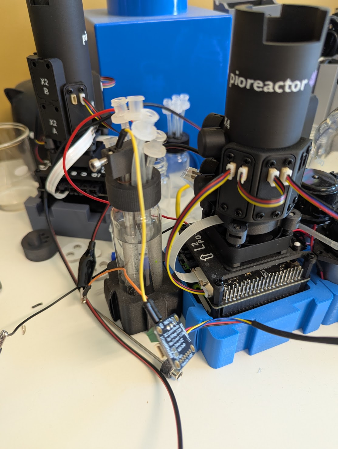
- Connected Adafruit INA219 current/voltage sensor to Pioreactor’s Qwiic port
- Electrodes (platinised titanium and stainless steel) pushed almost all the way into 40ml vial
- INA219 between cathode (negative) and Pioreactor
For the first run:
- Added 1g sodium bicarbonate to 40ml distilled water
- Put around 30ml of bicarb solution in 40ml vial
| Intensity |
Current |
Bus voltage |
| 0% |
0mA |
5V |
| 3% |
5.7mA |
2.3V |
| 5% |
7.8mA |
2.3V |
| 10% |
13mA |
2.3V |
| 15% |
18mA |
2.1V |
| 20% |
23.3mA |
2V |
| 25% |
28.5mA |
2V |
For the second run, I used Imperial’s (thanks @Teo !) minimal media (low iron):
| Intensity |
Current |
Bus voltage |
| 0% |
0mA |
5V |
| 3% |
5.7mA |
2.5V |
| 5% |
7.8mA |
2.2V |
| 10% |
13mA |
1.9V |
| 15% |
18mA |
1.7V |
| 20% |
23.3mA |
1.6V |
| 25% |
28.5mA |
1.4V |
For the third run, I used Imperial’s minimal media (high iron), and only filled the vial halfway. I also measured the voltage across the electrodes (cell I-V):
| Intensity |
Current |
Bus voltage |
Voltage across electrodes |
| 0% |
0mA |
5V |
0.03V |
| 3% |
5.7mA |
2.4V |
2.85V |
| 5% |
7.8mA |
2.1V |
2.98V |
| 10% |
13mA |
1.8V |
3.25V |
| 15% |
18mA |
1.6V |
3.44V |
| 20% |
23.3mA |
1.3V |
3.6V |
| 25% |
28.5mA |
1.1V |
3.78V |
So, what did I find?
- Current stayed constant for each intensity level for different solutions, volumes, and electrode coverage
- Current is identical across all three runs!
- Half-filled vial in run 3 is a deliberate control to raise cell resistance, and current still stayed the same
- Same results with and without 12V supply, as LED channels are on 5V rail
- Voltage changes across the electrodes for different solutions, which makes sense as we’re using a constant current output
- Velectrodes ≈ 5V - Vbus (Kirchhoff’s voltage law)
- Linear fit between current and intensity, valid for 3-25%:
Current (mA) ≈ 1.03 × intensity(%) + 2.6
- Note that it won’t be constant-current under all conditions - it holds only while cell voltage stays below the 5 V rail. In run 3 at 25% there was still ~1.1 V headroom, but more resistive media or electrode fouling would exhaust that sooner
- Cell voltage exceeds ~2.5 V across most of the conducting range (2.85 V already at 3% in run 3), which is the regime where ROS-mediated inhibition becomes a risk for HOB
I want to rerun this with MMO anodes (vs the platinized ones used here) to see if the lower OER overpotential reduces cell voltage.
1 Like
Just ran it again with MMO anode (iridium-tantalum titanium) and the cell voltage is around 0.3V lower 
With minimal media (high iron), half filled, with MMO anode:
| Intensity |
Current |
Earlier electrodes (cell V) |
MMO anode (cell V) |
MMO lower by |
| 0% |
0mA |
0.03V |
0V |
— |
| 3% |
5.7mA |
2.85V |
2.58V |
0.27V |
| 5% |
7.8mA |
2.98V |
2.70V |
0.28V |
| 10% |
13mA |
3.25V |
2.94V |
0.31V |
| 15% |
18mA |
3.44V |
3.11V |
0.33V |
| 20% |
23.3mA |
3.60V |
3.30V |
0.30V |
| 25% |
28.5mA |
3.78V |
3.43V |
0.35V |
Here is the case for switching from platinised to MMO (iridium-tantalum-coated titanium) anodes. IrO₂ is a much better OER catalyst at neutral pH, so it reaches the same current at a lower voltage - i.e. less overpotential, less ROS. My measurements bear this out: across matched runs, MMO sat ~0.3 V below the previous electrodes at every current.
One caveat on thresholds: I’ve been using ~2.5 V cell voltage as a rough “stay below this” figure based on our own “no growth above 2%” observation, but I want to be clear that’s a working hypothesis for our setup, not a literature constant. The MMO swap clearly reduces overpotential and therefore ROS; whether it’s enough to get us below the actual inhibition threshold is something we’ll only confirm with culture data.
1 Like
Wow, brilliant work @gerrit so there’s a clear case for us to move to MMO. And one could argue (as you correctly did before) that there is no need to make it easy to break the circuit for regular current measurement.
Other than cost and time for software development, would there be any disadvantages to making your setup standard? So including the INA219 current/voltage sensor in the AEP0.2 standard build and having it log current and voltage alongside OD & temperature in the pioreactor database. That would IMHO make reproducible, post-diagnosable experimentation much easier.
Thanks! Glad the MMO case is clear.
On making the sensor standard - I think this slightly inverts what the experiment showed. The goal was to prove we don’t need to measure current: it’s constant for each intensity regardless of solution, volume, or electrode coverage, so it’s fully predictable from the intensity selected:
Current (mA) ≈ 1.03 × intensity(%) + 2.6
So logging current would just be recording something we can already derive. Voltage is a fairer point, but a multimeter across the electrodes covers it when you want a reading.
To your question on disadvantages in addition to cost and software: BOM complexity and calibration overhead - all to capture a current value we can already compute exactly from the setpoint. I’d keep the INA219 out of the standard build.
Yes I was meaning more for voltage. But then the question is whether we can derive electrode voltage from bus voltage..? If there’s a solution that’s much cheaper/easier or can more accurately automatically log voltage when OD is logged if electrolysis power exceeds 0% that might be the winner.
Although we’re running tight on time for AEP0.2, so perhaps that’s for 0.3.
I think voltage is such a critical parameter for us to be assessing that it would be better, if possible, to not leave it up to individuals with multimeters to manually read and (hopefully) input into the log. Current is also critical, but as you have shown it could in most cases be derived from a power% look up table.
However if there isn’t a device much better/cheaper/easier than your INA219, why not just record current too?
With electrode voltage and current we can also derive cell resistance. Current gets us theoretical H2 and O2 evolution. Would that be worth adding to the SQLite database too, just for ease, so people don’t have to put their results into a spreadsheet to calculate them? It would be pretty cool if you could graph them in the Pioreactor interface.
Assuming this adds significant cost (BoM or kit assembly) to the AEP, I’d suggest we leave it out of the MEP, which we optimise for cost, so as many people as possible can run environmental enrichment cultures.